| This article describes the principle of calculation and installation of drawers on the TANDEM BLUMOTION partial extension system from Blum . Those. tandem guides with built-in closing closers. |
Article number in the Blum
: 550Н5000В.
The dimensions for fastening the guides on the side of the cabinet will be given taking into account the possible interchangeability of the drawers. The calculation and example are given on the basis of a three-drawer kitchen cabinet section (Fig. 2.). At the end, a fully parametric model of such a cabinet with all the fittings will be given for more detailed acquaintance. Model PRO100 in “*.sto” format.
! All calculations are made on chipboard with a thickness of 16 mm.
| Fig.2 | Cabinet parameters: |
Width 400 mm. Height 720 mm. (without legs), Facades - 3 pcs. Guides - 500 mm.
140x396 mm. - top. 284x396 mm. - lower ones.
To begin with, theory and diagrams from the official Blum
.
Fig.3
where, NL is the nominal length of the guide. SKL - box length. SKL = NL - 10 mm.
Fig.4
where, LW is the internal size of the cabinet (between the sidewalls). SKW is the length of the front or back part of the drawer (provided that this part is placed between its sides).
Fig.5
Diagram for calculating the height of the box.
Practical part. Calculation and installation.
In practical application, we will move a little away from catalog diagrams and make a diagram for ourselves. See Figure 6. Black numbers
- dimensions of the body, drawer sides, fronts and gaps.
Red
- dimensions for attaching guides.
Blue
- the size of the front and back panels of the drawers.
Green
- gaps in the drawer body between other parts.
Fig.6
With this scheme, the lower and middle drawers turned out to be interchangeable.
Tandem box diagram.
Fig.7
The Blum catalog suggests making boxes with a groove for fiberboard in all four parts, and then making cutouts in the front and back parts for the clamps. For what? It is enough to make only grooves in the sides of the box, and reduce the height of the front and back walls accordingly.
Fig.8
We take the length of the side of the box as according to the catalogue. Those. 500 mm - 10 mm = 490
mm.
Then, the dimensions of the drawer parts
:
- The sides of large drawers are 490 x 210 mm.
- Front and back parts of large drawers - 326 x 194 mm.
- The sides of the top drawer are 490 x 100 mm.
- The front and back parts of the top drawer are 326 x 84 mm.
When mounted to the side of the cabinet, the guides are fastened by 4 mm. from the front edge of the sidewall. Hence, the minimum
the depth size (the width of the side of the cabinet) should be = Length of the guide + 4 mm. For convenience, the depth of the cabinet should be considered as follows: Length of the guide + 10 mm. In our version, with a guide length of 500 mm. the depth of the cabinet will be = 510 mm.
1. Fastening the guides.
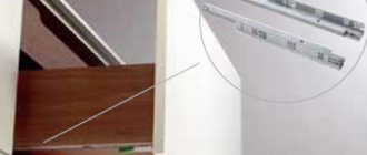
| TANDEM BLUMOTION partial extension slides from Blum | Marking. |
The guides are attached with an indentation of 4 mm. from the front end of the sidewall of the cabinet.
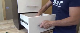
2. Assembling boxes.
| Cabinet frame with guides. |
| Groove for fiberboard in the sides of the drawers. Such a groove can be made using a hand-held plunge-cut saw. Cutting depth 9 mm. |
| Box details. | Croaking box. |
| Installing the bottom of a fiberboard box. |
| Tandem front locks. | The clamps are attached to the front panel of the drawer. |
| Fastening the clamp. | The clamp is in operation. |
| In the back panel of the box, on the left and right, blind holes with a diameter of 8 mm are drilled. to a depth of 12-13 mm. The hole is drilled at a distance of 8 mm. below and to the side of the corner of the part. | |
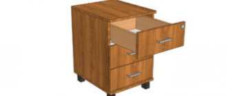
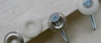
The design and principle of operation of hidden guides
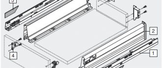
The flush-mounted guide kit includes:
- metal strips;
- metal bases along which the slats move;
- roller or ball mechanisms that facilitate the process of moving the slats;
- pins for fixing fittings to the box;
- fasteners.
Complete set of concealed mounting guides
Standard kits can be supplemented with:
- soft closing devices. Fittings with a closer allows you to extend the life of the furniture, since the absence of cotton when closing eliminates the possibility of damage to the material;
- return springs, allowing you to smoothly and quickly close the extended drawer;
- locking locks that facilitate the process of using and dismantling the structure;
- opening systems by pressing on the drawer front (Push-to-open).
All concealed installation guides are made from high-quality materials and differ in:
- accessibility. The cost of the accessories is significantly lower than the currently popular metaboxes and tandemboxes, and the functionality is much closer to the specified kits;
- quiet operation;
- possibility of fully extending the drawer;
- compactness and the ability to use the maximum amount of space of a piece of furniture;
- durability.
The disadvantages include the complexity of installation, but the detailed instructions included with the hardware kit and the availability of basic skills in working with a simple set of tools will greatly facilitate the process.
Selection of accessories
The key to long-term use of hidden guides is primarily the correct choice of fittings. To choose the right mechanism for a drawer, you need to consider:
- overall dimensions of fittings;
- maximum load;
- variety;
- manufacturing company.
Types of guides
Concealed mounting guides can be:
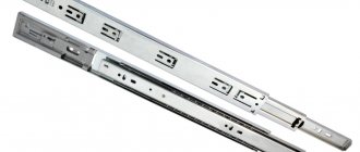
Ball guides are made of two or more metal profiles connected to each other using rolling balls (cage).
Hidden ball-type guide device
The advantages of this mechanism are the complete absence of noise during operation, the possibility of regulation and the ability to use with loads of up to 60 kg - 65 kg. A significant disadvantage is the high cost of fittings.
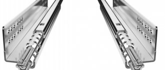
The roller mechanism is a simpler and cheaper design. The guides consist of two metal strips, at the ends of which rollers are installed to facilitate the movement process.
Roller type drawer guide
The disadvantages of this type of fittings are the limitation of the maximum load on the box to 25 kg and the presence of noise during operation, which can be eliminated with the help of rubber tires.
Determination of technical parameters of guides
For correct installation, before choosing, it is necessary to calculate the hidden mounting guides in order to determine the length of the fittings.
When calculating, you must take into account:
- view of the drawer front. There are furniture with overlay and inset facades;
- type of guide (partial or full extension).
The calculation is made in accordance with the manufacturer's recommendations:
- for drawers with an inset front, the optimal length of the guide will be determined as the difference between the size of the side wall of the case and 21 mm;
- for a drawer with an overlay facade, use the formula side dimension minus 3 mm.
The box can also be calculated based on additional parameters:
- internal size;
- internal dimensions of the case and so on.
Determining the length of the guides
Manufacturer's choice
The final stage of selection is determining the manufacturer of furniture fittings. It is recommended to purchase hidden guides made by:
- Austrian company Blum (world leader in the production of furniture fittings). The manufacturer specializes in the production of various types of guides. The advantages of the company are the production of a wide range of guides at various prices, including fittings with additional options, a long service life (Blum’s warranty is 15 years), and the addition of detailed instructions for self-installation;
Hidden guides from the world leader
- German company Hettich. The main difference is a more affordable cost. The quality of the fittings is practically not inferior to the world leader;
- Russian manufacturer Firmax. The company produces high-quality accessories developed by Russian specialists. Production is located in China, which reduces the cost of production;
- Italian company Fgv, specializing in the manufacture of retractable fittings and furniture hinges.
You can also pay attention to the fittings of the Russian company Boyard and the Polish company GTV.
Installation of hidden guides
So, each set of guides manufactured by Blum, Hettich, and so on, is accompanied by a hardware installation diagram, in accordance with which it is recommended to carry out installation.
Schematic illustration of the installation process
In general, installation of Boyard, Bloom, etc. fittings is done as follows:
- At the bottom of the box, the fastening points of the guides are marked with a guide lock in accordance with the recommendations of specialists specified in the instructions;
- the clamps are secured with self-tapping screws (included with the hardware kit);
Placement and fastening of the clamp for the guide bar
- opposite the clamps, holes are drilled for a latch hook, the size completely corresponding to this element of the retractable system;
- guide strips are installed;
Installing guide rails on a drawer
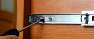
- the bases of the guides are installed on the side parts of the furniture with self-tapping screws;
Installing bases on the sides of furniture cabinets
- the slats are inserted into the bases.
The process of calculation and installation of hidden guides is presented in detail in the video.
After attaching all parts of the concealed mounting guides, the fittings are adjusted. As a rule, you can adjust the length and width of the slats.
Calculation of drawers for blum guides
Hello dear friends.
We have already talked about Blum tandems.
In this article I propose to consider the calculation of drawers for them.
If you have read the article about this sliding system, then you probably already know that drawers for it are designed and assembled completely differently than for other guides (the same “telescopes”).
The height of their side (dia2) and front (dia1) parts is different, and the bottom, which is slightly offset relative to the bottom, is made of chipboard.
As a result of this, protrusions are formed on the sides of such a box, between which the guides themselves should be located (in the installed version).
The size of such a protrusion should be within 13 millimeters.
So, let's look at the calculation using a specific example (it will be more clear this way).
All values proposed in the following will be measured in millimeters.
For example, we need to calculate a drawer for a box with a width of 550, a depth of 460, for an upper facade whose height is 150.
First, let's calculate the dimensions of the parts by width (depth).
In order to find out the width of the front parts (dia1), you need to subtract 42 from the size of the box body strip.
In this case, the width of the box body strip (550 wide) will be equal to:
550-32=518
Now, subtract 42 from this value and get the width (dia1):
518-42=476
Further, the depth of the part (dia2) depends on the size of the guide.
Since the depth of the box in which we are designing the drawer is 460, the guide for it is suitable for 450.
To find out the size (dia2), you need to subtract 10 from the size of the guide (450):
450-10=440
Now you need to decide on the height dimensions of the drawer parts.
When assembled, the tandem guides protrude down 15 degrees under the drawer (see picture below).
This must be taken into account when choosing the height.
So, if we take the height of the box (and, to be more precise, it will be the height of the parts (dia2)) equal to 100, and assume that there should still be a gap equal to 10 at the bottom of the guides, then let’s estimate how much free space will remain for the ceiling body strips on top:
150-100-15-10=25, where 150 is the height of the facade, 100 is the height of the drawer, 15 is the protrusion of the system from below, 10 is the free gap.
Great.
The body strips overlap and there is still a normal gap.
Well, the height (dia1) is determined taking into account the fact that the bottom of the box is made of chipboard, and it should be offset relative to the parts (dia2) by 13:
100-13-16=71
Well, finally, let's calculate the dimensions of the bottom itself.
The width of the bottom will be equal to the width of the part (dia1), that is, 476
The depth will be equal to the size of the part (dia2), that is, 440.
So, now you can write down the details:
- dia1 – 71x476 (2 pcs)
- dia2 – 100x440 (2 pieces)
- bottom – 440x476
But that is not all.
From the back edge of this box you need to make two holes with a diameter of 6mm, according to the dimensions shown in the figures below.
Thanks to these holes, the retractable system secures the drawer.
We will talk about how to mark the box for installing tandems in a separate article.
And that’s probably all, until we meet again!
Installation diagram for concealed mounting rails
We make markings on the sidewalls based on the height of the chefflots. The fastening line should be drawn at least 45 mm higher from the bottom of the cabinet or the edge of the lower shelf. Do not forget that the width of the sidewall should be 10 mm greater than the length of the guide.
The instructions indicate that the guide should be attached to the fourth hole to a depth of 37 mm. Having secured it in this way, the cheflot did not press tightly against the ends of the sidewall. I moved it by 39 mm and the gap disappeared. I used hidden mounting Boyard guides.
Roller elements
This mechanism is the simplest in terms of design and installation, and has a low price. It can withstand a load of no more than 25 kg, so it is unlikely that you will be able to store many things in such a box. If you incorrectly calculate and install the roller guides, they will quickly fail. Therefore, the work process should be approached with full responsibility.
First of all, based on the furniture drawing, precise marking of the mechanism attachment points is made. After this, a blind hole is drilled for the screw (its depth should be about 13 mm). Next, 2 more similar holes are created, the location of which is determined according to the drawing.
At the next stage, a guide element is placed on the drawer so that the end of the part, which does not have a roller, rests against the front wall of the drawer. The wheel should be placed at the back wall of the drawer. Using screws or screws supplied with the product, the roller guide is secured in place. The fastening is done in the same way on the other side of the box.
Next, they move on to installing the guides on the walls of the furniture itself. Here they are placed perpendicular to the facade of the furniture product. In this case, the ball should be in front, not behind. Typically, all guides have round and elongated holes for screws.
Many people fail to complete all the installation work the first time. In this case, you will need to disassemble the product and re-mark it to achieve the required result.