Today, in the field of electrical engineering, modular electrical equipment dominates everywhere, replacing all previously disparate standards in sizes and installation methods, and offering uniform installation rules. Of course, this approach has many advantages, which makes working with such equipment as efficient, safe and fast as possible.
Since modular equipment is usually installed in special electrical cabinets and panels, these products must also provide the possibility of their convenient and compact placement. It was for this purpose that a single format was developed for panels and cabinets, which became the din rail.
Gallery [ edit | edit code ]
DIN rail mounted terminals
Examples of fixing equipment on a DIN rail in the electrical panel of a three-phase power supply system, from left to right: terminal blocks (5 white for phase wires, 1 blue for neutral wire, 1 yellow-green for protective grounding wire), three-phase modular package automatic phase current limit switch , three-phase differential current device (RCD) with a leakage current threshold of 30 mA, relay and contactor for phase control and voltage protection]]
Installation of the machine
As an example, we can consider installing a circuit breaker to a mounting rail in an electrical panel.
There is a special clip on the instrument body for mounting on the rail
The rail is fastened to the panel body using screws. Electrical panels can be supplied disassembled, and are often equipped with an already installed strip.
Next, you should install the circuit breaker on the rail, for which one edge of the device is attached to the top of the bar and press the body of the circuit breaker until it clicks lightly. In principle, this completes the installation of the device.
Each modular device on a mounting rail can be freely moved in all directions horizontally. This allows you, if necessary, to change the location of the machine by simply moving it.
The wires to the circuit breaker located inside the panel are connected through a power cable and a wire coming from the electricity consumer.
First, the power wire is connected, for which you need to:
- Unscrew the fastening latch located on top;
- connect the power wire to the terminal;
- tighten the fastening.
To connect a consumer, the same steps are performed.
Installation on old panels
Installation of rails in old-type electrical panels is often carried out on surfaces that are not suitable for such work. There is nothing to be surprised here - Soviet-made shields were manufactured at a time when DIN rails did not yet exist.
The need for installation in an old electrical panel is due to the installation of new equipment in it - replacement or installation of additional circuit breakers or other devices:
- RCD;
- automatic machines;
- relay for phase control;
- voltage rise limiters;
- modular devices;
- small-sized electricity meters;
- packagers and other devices.
Unlike modern electrical panels or boxes, in which the DIN rail is placed in already prepared places and secured with self-tapping screws or bolts, you will have to tinker a little with old panels.
Installation of the rail in the old panel is carried out in the following sequence:
- two holes are made in the shield platform made of metal;
- threads are cut in the holes;
- the rack is secured using two bolts;
As a rule, there are enough holes in the platforms of old panels, so you can do without drilling.
How to choose the right electrical panel. shield modules
Distribution transformer substation. rp in electrical what is it. What is RP in electrical engineering?
When choosing an electrical panel, in addition to the design (internal, overhead) and the material from which it is made (plastic or metal), an important criterion is its dimensions, or rather the number of panel modules.
A module in a panel is considered to be one single-pole circuit breaker - an automatic circuit breaker, with an average width of 18 mm.
In a word, the maximum possible number of installations of single-pole circuit breakers in a switchboard is the number of switchboard modules.
Therefore, when purchasing a shield, it is necessary to at least approximately determine the modular elements of the shield - automatic machines, RCDs, meters, etc. and their quantity.
Here are the approximate numbers of spaces (modules on a DIN rail) for the main modular elements:
| Single-pole circuit breaker – 1 module |
| Single-phase two-pole circuit breaker – 2 modules |
| Three-pole circuit breaker - 3 modules |
| Single-phase RCD (Residual Current Device) – 3 modules |
| Three-phase RCD – 5 modules |
| Three-phase differential circuit breaker – 6 – 8 modules (depending on the manufacturer) |
| Modular electricity meter on DIN rail – 6 – 8 modules (depending on manufacturer and design) |
| Modular socket for panel on DIN rail – 3 modules |
| DIN rail terminal – 1 module |
| Modular bus for PE conductor DIN rail – 5 modules |
It is better to buy a shield with a small reserve in terms of the number of modules - you should not buy it “back to back”. For example, if the total number of modules is 12, then it is better to purchase a shield for 16 modules. This will provide the necessary reserve in case of changing the wiring diagram or adding new “points”.
If the panel is not completely filled with modular elements, in order to prevent foreign objects from entering the electrical panel, you can use special plugs for panels for empty modules. This will add greater aesthetics, improving the appearance of the shield.
Main purpose
The electrical panel consists of a number of modular devices (switches, automatic machines, indicators, sockets, etc.), each of which performs a specific function.
The panel socket is mounted in an electrical panel to allow connection of any electrical appliance to it during maintenance and repair of switchgear elements. Such an outlet is often used to connect electricity consumers located close to the switchboard. Often, during a control inspection of equipment, portable lamps are also connected.
The DIN rail socket is installed in buildings of various enterprises and office premises of large companies to create reliable electrical contact with the power plug of a device of any power during the arrangement of mock-up pavilions, test benches, etc.
Types of DIN rails
DIN rails are available in different lengths; they can be divided into shorter pieces as needed; for this purpose, markings in the form of a notch can be applied to a long rail.
DIN rails differ in profile shape, so they are marked - Ω, G and C type. To attach modular elements to the rail, its profile specially has jaws so that elements such as relays, controllers, starters and RCDs can be secured into the girth and securely fixed on it. Thus, the presence of DIN rails in a modern panel greatly simplifies the installation process of various unified modular devices. Many modern automation elements, power supplies and other electrical devices are adapted for mounting on a DIN rail. For example, the same machines simply snap onto the rail and no screws are needed. Counters, sockets, terminals are also easily mounted on a DIN rail.
DIN rails are found not only in panels. It can be used anywhere, in any place where appropriately standardized equipment needs to be installed. To do this, the rail has holes for fastening with self-tapping screws or bolts where needed. Before installing the rail, it is enough to take into account the width of the installed modules, then cut off the required piece of the rail with a hacksaw or grinder. In electrical panels, DIN rails are widely used due to the ease of maintenance of panels equipped in this way. It is enough to move the lock of the device, and it is removed from the rail in a second.
It was noted above that DIN rails can have different profiles, which are indicated by the corresponding letter. Thus, the most common type of slats is the Omega type slats (Ω -type), the edges of which are curved outward. In 2004, in Russia, the TN35 rail, an Omega-type DIN rail with a width of 35 mm, which is usually produced in standard pieces 2 meters long, was adopted as a national standard. There is also a smaller version of this strip, used for fastening terminals; its profile width and thickness are smaller.
G-type DIN rail
G-type DIN rail, the edges are bent inward, while one of the edges of the rail is narrower than the other, and the profile of the rail is similar to the Latin letter G. G-type DIN rails are used for installing terminal blocks, hardware clamps, etc. on them. The width of the G-type rail is 32 mm, the height of the long side is 15 mm, and the short side is 9 mm.
C-type DIN rail
The DIN rail is a C-type, the edges are curved inward, so the profile of such a rail is similar to the Latin letter C. This type of rail is usually used to install terminal blocks, hardware clamps, etc. on it. The width of the rail is 32 mm, height 15 mm.
End insulator
Another important point is that the insulated part of the terminal should always be on the left, the non-insulated part on the right.
That is, the exposed contact part should be located on the right side. When the terminal block is assembled, most installers stop at this design. The wiring begins.
However, do not forget about one of the exposed sides. All manufacturers make their equipment so that it is protected from accidental contact with live parts.
Therefore, when purchasing terminals, do not forget about the insulated end caps.
They are rarely sold individually; you will have to buy a whole set in a bag. Although often the entire assembly in the shield may require no more than 3 pieces.
Technically, such a product is called an end insulator. With a slight movement of the hand, it snaps into place thanks to its protruding parts.
End insulators can also be produced in various colors. But what if you don’t have end insulators, but you need to insulate the last right terminal?
The easiest way out is to place an additional empty terminal nearby. There is no need to connect wires to it. Although she will be naked, she will be without tension.
Or forcefully remove all metal insides from it. Another option is to use the ground terminal as the outermost terminal.
DIN rail mounting
What is cosine phi in electrical engineering?
The din rail has protrusions along the edges in cross-section, which are designed to hold the device installed on it. At the same time, it can move relatively freely along the rail. To prevent this movement, special stoppers can be installed on the sides, also specifically designed for installation on DIN rails.
But in panels used for mounting modular equipment, fixation often occurs due to the formation of external holes in the cover for the actually established number of switching equipment. To do this, the windows for the outer part of the equipment do not open completely; some of them are covered with easily removable curtains.
If there is less equipment in the shield, the remaining part of the window is covered with special plugs.
Modular circuit breakers, circuit breakers, and RCDs are equipped with latches that hold them on the DIN rail. To install, the upper groove of the device clings to one of its edges, and the lower part of it is pressed against the rail with slight force until it clicks. To remove the element, you need to use a flat screwdriver to move the latch down and remove it from the groove. On some hardware models, the latch is fixed in the open position.
Errors during selection and installation
When choosing a rail based on material and size, the type and weight of the devices to be installed on it are often not taken into account.
The main mistake when installing a DIN rail is neglecting the installation of plugs. Due to vibrations, equipment on DIN rails can gradually move. If the plugs are not included in the kit, you can secure the device with pliers - just straighten the jaws of the rack.
Also, during installation, the width of the device being fixed is often not taken into account, which leads to a lack of free space for fixing other devices.
Source: electric-tolk.ru
Detachable installation system for electrical equipment
L and n in electrics
The basic element of the Smissline system is plinths in two sizes for mounting six and eight standard modules, which are usually mounted on a standard DIN rail. By connecting the modules together, you can get a base of almost any length. Height limitation – 2 m (height of a standard distribution cabinet).
Conductive bars (10×3mm) are placed in the plinths. The consumer can create a 3-wire (L1, L2, L3), 4-wire (L1, L2, L3, N) or DC power system. In addition to the main power buses, two auxiliary busbars (5x2mm) can be installed in the base to power signal modules or additional contacts of protection devices or, for example, control circuits of contactors.
The busbars are powered through input terminals with a rated current of 160 to 200 A or using protection devices - RCDs, circuit breakers, etc. If the bus system is connected via a protective device, then the entire bus system is also protected.
In the distribution cabinet, the assembled busbar system can be installed either horizontally (traditionally) or vertically. Its vertical placement significantly saves internal installation space and provides power supply to the cabinet both from above and from below. All this, along with the absence of special outgoing terminals (outgoing wires are connected directly to the protection devices), simplifies design and reduces installation time.
Electronic catalogs
- Catalog ABB Basic M, E (modular devices and boxes)
- System pro M compact and other modular devices
- Selective circuit breakers Series S 750 DR
- Surge protection devices OVR
- ESB modular contactors
- E210 Series Switches, Push Buttons and LED Indicators
- Current measurement system CMS
- M2M Performance Indicators
- Smissline - system for detachable installation of electrical equipment
- Electrical equipment for residential premises and offices
Electrical panel diagram
For assembly, adjustment and further operation of the switchboard, it is necessary to draw up an electrical circuit diagram (PED). According to the rules, it must be present on the inside of the electrical panel door. The diagram shows the following elements:
- types, quantity and serial numbers of protection devices and electricity meters;
- wires and how they connect and interact with each other;
- rated currents of each protective device;
- connection of grounding bars, if any.
Electrical panel diagram for an apartment
Auxiliary elements and accessories
The accessories for the new System pro M compact range are universal: they fit all modular switches of the S200 and F200 series, as well as
RCBO series DS200, which allows you to effectively manage existing material resources.
The range is quite wide and includes auxiliary and signal contacts, remote releases and automatic reclosers, allowing the creation of various hardware configurations.
In all these configurations, auxiliary elements are connected without the use of any adapters. This increase in the efficiency of circuit breakers and RCCBs allows the use of innovative and integrated solutions in all cases.
Accessories for electrical installation (busbars, bus terminals and feeder terminals) allow connections to be made according to any scheme). The range of standard accessories (marking sets, terminal covers) allows us to satisfy all the requirements of electrical installation customers.
For circuit breakers S200 series, RCBO series F200, RCBO series DS200, DS201/DS202C
For RCBO series DSH941R
For circuit breakers of the S280 UC and S800 series
The practice of assembling an electrical panel or what GOSTs do not say
Strictly speaking, assembling electrical panels is a well-documented process in which everything is described in detail from how the electrical panel diagram should look to the tightening forces of the wires in the terminals. But knowledge of these rules does not yet know how to assemble an electrical panel without unnecessary loss of time, effort and numerous alterations. Therefore, we will list what needs to be taken into account in addition to regulatory documents (they will be needed to hand over the finished facility to power engineers before connecting the meter), and reading GOSTs.
- Preparatory work. Installation of wires into the terminal blocks of the panel takes from 1 to 3 minutes per wire. In this case, stripping the wire can take 10 minutes if you do this operation “in weight” inside the shield. Measure the wires, strip the ends, pre-bend the toughest ones according to the template. And it’s faster and more correct to mount connections according to the diagram, without being distracted by little things, after which you’ll have to remember what to screw where.
- The length reserve of all wires that cannot be correctly assessed before installation in the panel. If you think that 20 centimeters are extra, carefully remove them behind the DIN rails. They will come in handy someday later.
- The cross-section of the wires should decrease from the power input (input circuit breaker) to the meter and further to the protective circuit breakers and the section of the circuit with the load. We discussed which cable to choose in another article, but remember, the cross-section of the ground wires in the panel must be no less than that of the phase wire from the extreme circuit breaker.
- Twisting and coiling of live wires is unacceptable. It is also necessary to separate the power and neutral wires on different sides of the shield.
- It is imperative to take into account the location, if necessary, choosing a non-flammable box designed for installation in a wooden house.
- In any case, the assembly of electrical panels begins with checking the installation of circuit breakers. meter, input shutdown device (switch) to check the sufficiency of space and the correct placement of all devices. Installing the machine is easy if you have a place to install it. The ideal option would be a trial assembly without switching with marking of the installation locations of the devices. When working, this will help you not waste time, understanding that the electrical panel circuit is implemented correctly.
Before you think about how to assemble an electrical panel. We, of course, brought the cables from the loads (sections of the circuit) to it, while correctly placing them at the entrance to the panel.
The photo below shows the correct example, in which the connection of each line can be provided with any margin for placing the wires inside the panel.
The most correct thing to do when creating an electrical panel diagram would be to allocate separate lines for independent consumers. In this case, extra cables will not be “extra”; it is actually insurance against overloads and the possibility of duplicating overloaded areas. Usually at the electrical wiring design stage it is difficult to detail the number and power of devices. Therefore, a safety margin in the sense of independent sections of the electrical network will not hurt. Of course, you shouldn’t overdo it in this sense.
Perhaps these are all the main rules. It remains to provide for the possibility of quick dismantling of the shield, turning off the power both inside and outside the shield, and reasonable protective measures. After that, assembling the electrical panel will not be a difficult task.
Features of application
DIN rail is a foreign invention that takes its name from the German standard designated DIN 43880-1988. In our country, their use is regulated by GOST R IEC 60715-2003. These products are sometimes called mounting rail. The full name looks like this: “mounting rail for fixing protective devices in low-voltage distribution and control equipment for electrical networks.”
In accordance with this definition, its scope extends to the following cases:
- the need to install electric meters and other types of measuring equipment in the distribution cabinet;
- the need to place protective equipment there (RCDs, automatic circuit breakers, voltage relays, etc.);
- If desired, install special connecting fittings into the cabinet.
The decisive factor determining the capacity of such a rail is the width of the machine module or similar protective equipment installed on its base.
When assessing the width of the machines, they are based on the specific number of protective devices used in the panel, which can have a single-pole or multi-pole design. The second option concerns three-phase networks. In general, its use is limited to this particular set of functions, but in certain situations other directions for using the DIN rail are possible.
Dimensions and installation method
In domestic conditions, standard strips with a profile width of 35 mm (TN 35), having a shelf height of about 7.5 mm, are traditionally used. Different versions of the product may differ in the declared thickness of the profile (1-1.5 mm) and the diameter of the holes filled during perforation (4 or 5 mm). To attach them to the distribution board guides, you will need bolts of the appropriate size.
The installation product is fixed at the two extreme points of the strip in such a way that there are no parts protruding beyond the cut of the guides. That is, the length of the workpiece is selected exactly to size, for which the side excesses are cut off in advance.
Let's look at an example of how to hang a cabinet in the kitchen using a mounting rail.
Tools you will need:
- Impact drill or hammer drill.
- Several dowels with a diameter of 10 mm and a length of at least 6 mm.
- Two canopies and a mounting plate.
- Metal scissors or jigsaw.
- Concrete drill with a diameter of 10 mm.
- Drills 4 and 2 mm.
Fastening awnings
Let's prepare a cabinet for attaching awnings. To do this, if it is not removed, dismantle the back wall. It is usually made of fiberboard. We insert the canopy inside the cabinet and make sure that its upper part fits snugly against the cabinet body.
The hook, when released, should extend beyond the cabinet body by 4mm.
Use a 4 mm drill to drill a through hole for attaching the canopy.
We do not drill the second hole for fastening the canopy through it, but go through it with a 2 mm drill to screw in the screw.
In practice, two fastenings use screws, but for greater reliability it was decided to use a through screw and nut. The disadvantage of this method is that the screw head will be visible on the side of the cabinet. But even with ordinary screws the cabinet will not fall off.
When the hole is ready, fasten the parts with a screw and washers.
You should not clamp them too tightly so as not to break the canopy body.
We screw the screw into the second hole.
We do the same on the opposite side.
There are “left” and “right” canopies, and they need to be inserted accordingly.
The body is marked with the letters “L” and “R”.
Having secured the canopies to the side walls of the cabinet, we cover the back wall of the fiberboard with a panel, cutting out the places where the hooks exit. This can be done either with metal scissors or with a regular jigsaw.
We nail the panel to the body with thin nails.
Installing the mounting plate
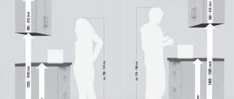
The cabinet is prepared, we determine the height of the mounting plate. It should be assumed that the distance from the sink or countertop to the bottom of the cabinet in the kitchen should be 500 - 600 mm. If this value is less than 450 mm, the cabinet may interfere with work on the work surface of the kitchen countertop. Consider the height of the owner and the depth of the closet. When we have decided on this value, we add it to the distance from the bottom edge of the cabinet to the hooks. This will be the height of the mounting plate.
Practical use of DIN rails
Currently, the use of DIN rails is provided for in most electrical panel designs. All electric meters and other modular switching equipment are also available with ready-made mounts, with the ability to be placed on a rail. Fasteners are special clips made of metal or plastic that secure and secure equipment mounted on a DIN rail. The cost of DIN rails, depending on their parameters and material, differs several times.
The main advantage of electrical panels that use DIN rails is the simple and convenient installation of modular equipment of various modifications. Maintenance of such shields is also simple. For example, to replace, you just need to unscrew the terminals, remove the wires and remove it from the rail.
In order to install a new electrical device into the electrical panel, all steps must be performed in the reverse order. Simply click the device into the rail, insert the wires and tighten the terminals.
The household series of switching equipment has another name - modular. The reason for this is that all circuit breakers, switches, and RCDs are assembled from modules of the same width. Their overall dimensions are approximately the same.
An important property of the modular series equipment is that its mounting is unified. Let's remember how old circuit breakers were attached to the surface. To do this, it was necessary to drill holes, sometimes even cut threads into them. And also use fasteners: screws, nuts, washers. Not only is this inconvenient, but it is also unsafe. In an electrical panel, part of which is energized, replacing the circuit breaker is carried out with a certain degree of risk. A dropped screw can short-circuit a phase to the housing and cause a short circuit. And both an amateur and a professional electrician can drop it.
No screws are required to fasten electrical equipment of the modular series. All of them are installed on a standard metal strip. It's called a din rail, let's figure out what it is.
The abbreviation DIN comes from the abbreviation of the name of the German Institute for Standardization, Deutsches Institut fur Normund. Strictly speaking, this abbreviation is used not only to designate rails, it is used in other areas to mark standard connectors, fastener parameters, and so on.
Maintenance of electrical panels
Even a correctly assembled and approved electrical panel requires maintenance. The frequency of these measures is determined based on operating conditions, requirements for uninterrupted operation and complexity of the equipment.
The main maintenance activities for the switchboard include the following:
- visual inspection of wires under load;
- listening to the live panel for crackling or unnatural buzzing sounds;
- tightening screw connections and terminal blocks (with stress relief);
- cleaning switchboard equipment from dust and other pollutants;
- checking the presence of tags on the wires and their compliance with the electrical diagram;
- measuring the temperature of individual devices and contacts;
- control of the presence of seals on measuring instruments (in the case of commercial accounting).
Without electrical panels it is impossible to build complex electrical networks. You can’t do without them in a small one-room apartment. With their help, protection and automation devices (RCDs, current and voltage relays) are assembled compactly and in one place. Thanks to this, electricians have convenient access to key power control and distribution units.
The assembly of electrical panels begins with design, drawings and diagrams. This takes into account the dimensions of the devices included in the system. At the same stage, the location of the equipment is also considered, because high humidity and dust can damage the internal electrical devices of the panel.
#7 Modules and various small items for DIN rail
Greetings! We will talk about various modules and chips that everyone knows will help assemble the shield.
I will not write about the need to use high-quality machines, RCDs, this is discussed in other posts in our community.
Let's start with something simple - wires.
, which we will use to combine the filling.
For these cases PV-3 (PuGV)
, due to the fact that it is multi-core, it is quite flexible.
a stripper to strip wires.
. This tool can quickly strip a wire over a certain distance without damaging the core and will do it in just 3 steps, don’t you believe it? See for yourself)
The stripper I have is not the best option; it copes poorly with large wires.
To avoid “fluffing” of the stranded wire in the machine, we use a crimper (press pliers or simply crimping)
They are different, they crimp only certain tips of a certain cross-section - we pay attention to this! We will need NSHVI lugs, this is what the wire crimped with them will look like:
We will need NSHVI lugs, this is what the wire crimped with them will look like:
Connection of machines. A splint (comb) is used here. This solution will allow you to get rid of unnecessary wires, and will also add reliability and aesthetics.
If such jumpers are required, then crimp two wires directly with a special tip NSHVI (2).
There are special machines; they have a double clamp for connecting the comb and wire:
In the photo there is a special bus for 2 phases (or one phase and zero), there are also combs for 3 phases.
Stopper for din rail
. As the name implies, it fixes everything that is installed on the rail, preventing warping and displacement.
Terminal blocks
. With their help, we simplify the connection of the shield. It will be enough to connect the input and consumers to the terminal block intended for them.
Less important/specific modules will come next)
DIN rail socket.
Might come in handy sometimes. In one of the videos I saw how it was used well.
Indicators.
You can indicate the presence of phases (phases), relay activation, etc.
Call
. I think there is no need for comments here)
Voltammeter.
We monitor power consumption. A good solution would be to install it in several phases.
Voltage relay
– Protection against high or low voltage, which can be dangerous for equipment. This is especially true for houses with old wiring, but this has already been discussed in one post from our community
Reversing switches
– with the help of switches, you can organize manual switching to the backup input (for example: you can switch the power supply at home from the local electrical network to a generator), they were also written about in one post.
Impulse relay
– we organize the switching on/off of the load (for example, light). Switching occurs after a “pulse” (power supply and shutdown), with their help you can control the light from several places.
Signal contacts
– modules for automatic machines, which allows you to determine the position of the automatic lever/RCD/Differentiator, etc..
Cross modules and distribution blocks
– needed for more convenient distribution of power in the switchboard (especially in three-phase).
Phase control relay
– Protection against violation of phase symmetry, phase loss, violation of phase sequence, etc.
Thermostat and heater on DIN rail
– Necessary for shields that are installed outdoors.
Priority relay.
This module will be useful for those who do not have enough allocated power. If the power consumption is close to the peak, then various loads will be switched off.
Time relay –
turning on and off the load at a certain time
Counters
- they are compact, especially for installation on a DIN rail.
Switchboard equipment
Power transmission and distribution panels perform many tasks. Protection of wiring from overcurrents, electricity metering, switching of consumers over time - this is only a small part of the functions for which panels are designed. Therefore, their contents are no less diverse.
Electricity metering devices
Present in every residential switchboard and in some substation switchgears. The meter is designed to record the amount of electricity consumed by the consumer.
A 220 V household meter has 4 contacts for wires. If you connect step by step from left to right, then their purpose is as follows:
- Lin. Input of the supply phase of the input cable.
- Lout. Phase output to consumer.
- Nin. Neutral wire input.
- Lout. Output of the neutral wire to the consumer.
To install a three-phase meter, you will need to connect 8 wires. They are connected taking into account the purpose of the device terminals, which is described in the technical documentation.
Circuit breakers
They are installed at the input in front of the meter in every household electrical panel. Not less common in industrial control panels. Circuit breakers are the most common short-circuit and overcurrent protection devices.
At the entrance to the apartment, a switchboard with 2-pole circuit breakers is installed. For individual group consumers - single-pole. There are also 3 and 4 pole devices.
The task of the machines is to de-energize the line if there is a short circuit or overload. In case of a short circuit with high currents, tens of times higher than the rating of the machine, it turns off instantly. With small overloads of 1-2 In, the machine will work after a while.
General Electric modular machines
Additional Information. The rated current and tripping current of a circuit breaker are two different things. By rated we mean the current at which the device remains switched on indefinitely. For example, for a C16 machine it is 16 A. The operating current is always greater than the rated one.
Differential circuit breakers and RCDs
They are also used in apartment panels, but are much less common. RCDs and automatic circuit breakers are usually installed in new buildings and when modernizing old electrical networks.
RCD is used to protect people from electric shock. The electronic filling of this protective device is able to understand that someone has touched a live wire and instantly turn off the dangerous potential. Fire protection RCDs are distinguished separately. They protect wiring from fire, but work on a similar principle.
The difavtomat is a combined device. It combines the functionality of a circuit breaker and a residual current device in one housing.
Voltage control relay
Belongs to the class of protection devices. The control relay protects the consumer from excessive voltage sags or surges, which can damage expensive consumer electronics. RKN is especially relevant for small cities or remote settlements, where tension can spread in an unpredictable way over a wide range.
In the electrical panel, this device is installed after the input machine and metering device. If the voltage is outside the permissible limits, it turns off the supply phase wire. The voltage control relay has an operating range setting. That is, it is possible to independently indicate at what network voltage the apartment is connected and at what it turns off.
Grounding and zero bus
Zero and grounding buses are used for ease of installation and clarity of the assembled panel diagram. The use of these elements is a requirement of the PUE. Therefore, they are provided in most modern electrical panels.
The grounding bus is connected to the building's grounding loop. In the diagram it is denoted by the Latin letters PE. And yellow-green wires are connected directly to the grounding bus in the shield. In houses with old PE wiring, the bus may be missing.
The neutral bus is electrically connected to the neutral conductor of the input cable and the neutral of the transformer substation. It is necessary for the operation of household single-phase electrical appliances. In the diagram it is indicated by the letter N. And in the shield, wires of blue or black (less often) color are connected to it.
Important! If you touch the zero bus, it will not give you an electric shock (do not check). However, when working with it, special care must be taken. If you disconnect the common neutral wire coming to it from the N bus, then a voltage of up to 380 V will flow through the apartments powered by the switchboard. At the same time, some residents are likely to burn out some of their expensive household appliances. And the blame will fall on the person who mistakenly rejected the total zero.
Comb tire
Designed for quick, simple and intuitive assembly of the electrical panel. The comb bus is essentially a jumper. It is installed in horizontal rows of circuit breakers for their simultaneous connection.
If there are 10 machines standing in a row, and each one needs to be supplied with a phase wire, then 1 comb is enough. Previously, for this you had to make special jumpers with your own hands.
RX Legrand comb tire
The comb busbar is made of copper. If desired, you can cut it yourself to the desired size or remove excess leads (teeth) with pliers. The outside of the comb is insulated with a layer of plastic, which makes it much safer than outdated jumpers.
Terminal blocks
They are found in complex devices where dozens or more elements (automatic machines, relays) are used. Terminal blocks are most common in low-current equipment. They also make the circuit easier to install and understand. With their help, it is possible to quickly disconnect or connect one or another element of the electrical panel.
Some terminal blocks are produced in assembled form. If necessary, they can be expanded as a constructor to the desired size. Therefore, they will never take up extra space in the shield.
Trays for wires
Typical for large boards with complex equipment. Trays are used for compact wiring. They are similar in design and purpose to cable ducts. The trays have a cavity for wires and a lid with a latch.
The difference between cable ducts and trays lies in the holes in the side walls. Regular cable channels do not have them. Trays have it. The holes are intended for the output and input of additional wires.
Other devices
Other equipment refers to devices that are not present in every panel. However, without them, some electrical systems cannot operate. Conventionally, these devices are divided into 5 categories:
- Switching devices (relays, magnetic starters, contactors, disconnectors). Designed for mechanical switching on and off of electrical circuits.
- Protection devices. In addition to the listed machines and RCDs, this category includes all kinds of current and voltage relays, powerful fuse links and low-current fuses.
- Frequency drives. They are installed in panels of conveyors, elevators and other equipment where it is necessary to control the rotation speed of motors.
- Indication and alarm. Various indicator lamps displayed on doors, electrical panels, sound alarms, sirens, flashing lights.
- Devices for interacting with other equipment via digital and analog communication channels. For example, RS-485 to USB interface converters, various expansion units. Needed for operation of switchboard equipment with PC programs and various portable diagnostic devices.
USB-RS485 to DIN Rail Converter
Calculation of panel dimensions and DIN rail length
With the advent of globalization, electrical equipment manufacturers were forced to standardize the dimensions of their products. All automatic devices, RCDs and modular devices have standardized dimensions.
This approach allows you to easily calculate its dimensions at the shield development stage. For example, a standard circuit breaker is 17.5 mm wide. If, according to the diagram, it is necessary to install 10 group circuit breakers at the bottom of the switchboard, then a DIN rail with a width of 175 mm (17.5x10) should be left under them.
Two-pole circuit breakers and RCDs are 2 times larger in size, equal to 35 mm. Three-pole devices have a width of 52.5 mm (17.5x3). And four-pole ones, respectively, are 70 mm.
There are also larger modular devices. Their size is also a multiple of the width of 1 module, that is, 17.5 mm. For example, electricity meters. Their width is 6-8 standard modules (105-140 mm).
Let's make a project
It is better for a non-professional to do this when all the wires have already been laid and all the circuits have been taken into account. At the development stage, we must create working drawings for ourselves, according to which subsequent work will be carried out, and also find suitable specifications for components and accessories.
Consumer accounting, group creation
You need to start by compiling a complete list of consumers, if this was not done during installation of the wiring. This will not include the iron or sconce in the hallway, but each wire coming to the switchboard, which must be recorded and designated with a number.
Residential power supply systems follow the same principles and are therefore similar to each other. The power sockets of each room are powered separately and the lighting of the rooms is separately powered. Some household appliances do not connect to junction boxes; their wires go directly to the panel. This is not always explained by their increased power, like that of an electric stove, for example. Isolation may be a consequence of increased protection requirements (the boiler must be connected through a very sensitive RCD), or the need to turn off the device locally (an air conditioner for maintenance).
Sockets for each room must be powered separately
So, here is a typical list for a modern three-room apartment:
- sockets in the bedroom;
- sockets in the living room;
- sockets in the nursery;
- sockets in the bathroom;
- sockets in the kitchen;
- sockets in the corridor and hallway;
- connecting a washing machine;
- boiler connection;
- air conditioner connection;
- connecting an electric stove;
- lighting in the bedroom;
- lighting in the living room;
- lighting in the nursery;
- lighting in the kitchen and bathroom;
- lighting in the corridor, hallway and balcony.
Of course, if each circuit is “put” on its own machine and run through an RCD, it will be both more reliable and more convenient. But issues of compactness and efficiency are also important. We can combine some of the circuits listed above if the load is moderate and separate automation is not needed. For example, points 1 and 2, combinations 11+12+13 and 14+15 are also possible.
After combining, we transform the list into a simple table, where we will then enter data on the ratings of machines and RCDs.
Features of choice
When selecting the necessary device, the following nuances are taken into account:
- What is a pulse relay: principle of operation, types, description of devices and connection diagrams. 155 photos of pulse-type relays and video installation instructions
- Photo relay for street lighting - selection criteria, tips for connecting and placing the device (135 photos)
- Pulse protection device: classification, limiter connection diagram and tips for choosing a device (155 photos)
- Particularly popular are 1 mm steel slats with a length of 1 m. This is a universal option that is cheaper than its aluminum counterpart.
- The plates are cut to the size of the shields. The choice is made according to the dimensional characteristics of the box where installation will be carried out. For new fastenings, the size of the strip should include a margin.
- When installing modules for DIN rails, a 10-15 mm plate plus a margin is usually taken.
- If you buy assembled panels, then they already have slats of the required size installed.
The rail is fastened along the edges. Sagging should be avoided; dimensions must clearly correspond to the installation location. If necessary, it is advisable to use special holders.
DIY assembly steps and rules
Before you start assembling a 220 V or 380 V electrical panel with your own hands, you must create all the conditions for comfortable work. It is necessary to check the availability of tools and a complete set of equipment, fasteners, and cable products. Prepare a flashlight with a charged battery. You need to check the circuit and determine the correspondence of the picture with the wires laid out.
The panel installation work is divided into several stages:
- Preliminary work. These are all operations in direct preparation for the installation of an electrical panel. To do this: Remove the plugs and drill additional holes (if necessary).
- The door and wall panels that will interfere are dismantled. All rails and terminal block are installed.
- Hinges are screwed in for installation.
The cables must be connected in order. From which side this is done does not matter. You need to follow some rules:
- When installing an electrical panel with your own hands, all wires are laid horizontally and vertically.
- Bends - at an angle of 90 degrees.
- The veins are exposed by about 10 millimeters.
- The lugs are crimped onto the flexible wire.
- All connections are pulled tight.
- According to unwritten rules, the input is connected from above, consumers from below.
- Unstripped areas of wires should not be clamped into terminal blocks.
- For ease of installation and subsequent operation, groups of wires must be assembled into bundles and secured with plastic clamps.
Power is connected to the input device after the voltage has been completely removed and checked with an indicator. The cores are pulled tightly onto the terminals. If there is a ground, the contact is connected to a separate terminal block. After the introductory machine, the metering device is connected and then in groups.
At the final stage of assembling electrical panels, it is necessary to visually check the correctness of all connections, the absence of unnecessary wires and the quality of the contacts, by tugging them with your hand. After this, food is supplied to each group in turn. RCD testing is carried out by pressing a button and checking that there is no power in the corresponding group. If no problems are identified or after they have been eliminated and rechecked, all removed parts are returned to their place and the voltage is switched on to full load.
Correct installation and selection of appropriate components guarantees trouble-free operation of the residential energy system. Not only comfortable living, but also the safety of human health and even human life depends on this.
How to use it in electrical
This rail is very popular these days, and therefore most of all panels have a compatible design, as well as other electrical equipment with ready-made mounts. And, as already noted, the main advantage is convenience. This is reflected not only during installation, but also during the maintenance or replacement of equipment.
Installing the rack
First of all, you need to understand how to install the rail. Installation of the strip is carried out as follows:
- Determine the location. It is necessary to take into account not only the profitability of the current situation, but also its strategic benefit, so that in the future there will be no need to reassemble the entire structure.
- Select the required distance for the screws if the structure does not have factory perforations. If you have extra space, it is recommended to take a plate with a reserve. The unused portion can be folded over to fit into the desired space.
- Fix the bar and check its reliability.
Now that the main structure is ready, all the necessary electrical elements can be placed on it.
Installation of the machine
To confirm the mounting on a DIN rail, let’s look at how to fix 1 machine:
- Check the integrity of the installed strip. By default, solid ones are considered the most durable, because the holes are made personally by the builder.
- Hook the machine with one edge on the upper or lower part and press on the opposite side to fix it. It is imperative that there is a click, as it informs that it is securely fastened. In addition, it is recommended to check the clamp before purchasing.
- Ready. The installation is now complete and, thanks to the design, the machine can move freely left and right if necessary.
As follows from the instructions, the fasteners are really simple and can save as much time during replacement and maintenance as during the initial installation.
What does it look like?
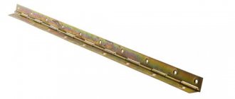
A photo of a din rail clearly makes it clear that it is an elementary mounting strip - a profiled metal strip, cast or with specially made holes for fixing to the surface.
The name of the bar was the abbreviation of the developer of the useful device - the German Institute for Standardization or Deutsches Intitut for Normung - abbreviated as “DIN”. There are other variations of the name: lath, strip, rail, tire and profile.
Nowadays, mounting plates are so popular that almost all electrical equipment, even at the production stage, is equipped with special clamps for mounting on a din, greatly facilitating the work of electricians.
What sizes can DIN rails have?
All DIN rails have received standard sizes; they are never produced differently. Dimensions are determined according to the following state standard GOST R IEC 60715-2003, the width in this case can be:
It is worth noting that the omega din rail can have three sizes, because it is universal and is used everywhere. Find out how to take readings from a two-tariff meter.
The minimum length of the DIN rail is 7.5 cm and can accommodate one circuit breaker. The maximum is 2 meters, this length is enough to install 4 shields.
There are still slight differences in the manufacturing method; the planks can be:
- With holes.
- Solid.
The former make it possible to simplify the installation process; just screw the rail into the finished holes. The distance between the holes is 10-20 mm, which can be called optimal.
Cast (solid) ones are considered more reliable; even under heavy loads they do not bend. Even several machines can be installed on such DIN rails. This is how you can mount all devices during electrical installation.
Types of electrical panels
The dimensions of the shield fundamentally depend on the number of electricity consumers that are powered by it. Standard shields in a house are usually small. Their largest side does not exceed 50-60 cm (we are talking about modern IEK type boards). Industrial shields can be as tall as a person and several meters wide.
Metal body IEK
There are also differences in terms of installation. Panels for outdoor installation are mounted on walls using dowels. They protrude from the surface by 10-20 cm. But there are also shields for internal installation. They are walled up in the walls so that only their door is outside. In both cases, the contents of the panels must be accessible to maintenance personnel. As a rule, the door is locked with a key included with the switchboard.
Kinds
They are produced in different sizes and shapes. It is clear that you need to install a short rail in a small shield. And the long one is sometimes even called DIN rail. The rail is fastened with screws or bolts, for which the manufacturer has already drilled a series of oblong holes on it. They are also produced without holes, which, in general, gives a little more hardness. During installation, you will then need to accurately drill where the rail will be attached to the base. Material - aluminum or steel, galvanized or stainless steel
Actually, reliability is important, and not physical lightness, so that the rail firmly holds the modules installed on it, because this is most often very important for powering the apartment, and for its safety, and for the equipment. What needs to be installed once, but with 100% confidence in the results
The manufacturer plays a role. Actually, its production culture. This can always be seen by the absence of burrs, strictly maintained linearity of shape, as well as the size, thickness and quality of the metal. There are several popular manufacturers: ABB, IEK, DKS. But many well-known companies are engaged in the production of electrical accessories, so it is better to be guided by considerations of a fundamental nature when choosing.
Three profiles are available.
Ω-shaped (omega). We use it most often. Machines and metering devices are attached to it.
Omega DIN rail
C-shaped. Hardware clamps and terminal blocks are placed on them.
DIN rail C
G-shaped profile. Almost the same as a type C rail, only for specific clamps.
DIN rail type G
Sealing of terminals
When you have assembled the entire terminal block and connected the wires, the energy supply organization may require that all live parts be sealed so that later it will not be possible to make changes to the metering circuit.
For this purpose, plastic transparent boxes are used. In the fastening places where the “lambs” or nuts are tightened, there are slots for fishing line or wire from the seal.
Photo of din rails
Quick installation of electrical equipment - only on DIN rails!
We offer perforated slats:
- 75 mm;
- 300 mm;
- 500 mm;
- 1000 mm;
- 2000 mm.
These are mounting rails made of Omega profile steel with a width of 35 mm. The model was originally developed in Germany and was called DIN rails (DIN - Deutsches Institut fur Normund - German Institute for Standardization). Since 2004, according to GOST R IEC 60715-2003, it has been the standard mounting profile in Russia.
Usage
Mounting mounting DIN rails are designed for installation of modular electrical equipment.
Used for fastening:
- circuit breakers;
- differential automatic machines;
- electricity meters,
- relays, contactors and starters;
- cross-modules and terminals;
- electrical outlets;
- switching equipment.
Using products of this type, equipment is installed in electrical panels, cabinets and installation boxes. The use of DIN rails and the compact dimensions of electrical equipment and products make it possible to place a larger number of equipment in standard housings. This saves installation space, and ease of installation saves time.
Classification
Dinreyks differ in:
- material of manufacture (steel, aluminum);
- length (from 75 to 2000 mm);
- presence of perforation (solid, perforated);
- profile thickness (from 0.8 to 1.5 mm);
- profile shape (omega, G-rail, C-rail).
Assortment presented
In the 220pro store you can buy galvanized steel DIN rails made in Russia and Italy. Profile width 35 mm, height 7.5 mm, Omega type.
Depending on the thickness and length, products are divided into several groups according to load.
For light loads
Galvanized steel - 0.8 mm thick, aluminum - 1 mm, length 75-100 mm. Purpose - for fastening individual elements (automatic machines, RCDs, power supplies).
For medium loads
Steel - 0.8 mm, aluminum - 1.1 mm, length 300-1000 mm. Used for mounting automatic machines, RCDs, power supplies, cross-modules, relays and modular switching equipment.
For increased loads
Steel - 0.8 mm, aluminum - 1.4 mm, length 500-1000 mm. For fastening any type of product: automatic machines, automatic devices, RCDs, frequency converters, contactors and starters, power supplies, cross-modules, relays, power circuit breakers.
For maximum loads
Steel - 1.0 mm, aluminum - 1.5 mm, length 1000-2000 mm. Used for installation of heavy equipment: frequency converters, contactors, soft start equipment, power circuit breakers. The best option for professional installation, with a minimum amount of trimmings.
Different types and additional accessories
In addition to the standard width of 35mm, smaller slats of 15mm with a height of 5mm are available. They are used for installing terminals and other light electrical installation products.
A dinrail holder (bracket) is used as an additional accessory. Installing the holder allows you to “plant” the rail at an angle, turning the lower side “facing” the master conducting the work. When attaching terminal blocks or cross-modules to such an inclined DIN rail, an electrical installer gets convenient access to groups of contacts. This makes it easier to connect cables, especially when distributing one power supply to a group of consumers.
Advantages of using DIN rails:
- standard sizes (suitable for all types of equipment and electrical products);
- safe installation of open electrical wiring;
- suitable for electrical panels, boxes;
- high speed of installation of individual modules on the rail (3-5 seconds);
- quick installation and dismantling of equipment;
- perforation for easy screw mounting;
- notches along the length of the slats for cutting to size;
- installation of a large number of equipment in a small area, without loss of connection quality;
- affordable prices;
- compliance with GOST and IEC requirements.
Very often, when carrying out electrical work, the need arises for high-quality fastening of any electrical devices. DIN rails are widely used as fastening materials. However, many people do not know what it is and what a DIN rail is for.
Load characteristics of DIN rails
As you can see in the photo above, a DIN rail is a profile product and is a priori designed for high weight loads compared to a simple plate. However, there are load characteristics of DIN rails that you need to know.
- Aluminum slats 1 mm thick, designed for the installation of individual modular devices, such as circuit breakers, ouzo, power supplies. Before use, cut into short pieces.
- Aluminum slats with a thickness of 1.1 mm are designed for the installation of single modular equipment in rows.
- Aluminum slats with a thickness of 1.4 mm are designed for the installation of modular equipment of any weight.
Steel slats with a thickness of 1.0 mm, a load analogue of an aluminum slatted 1.5 mm, can withstand maximum loads and have no restrictions on installation.
I note that manufacturers of electrical panels can equip the panels with rails with other profiles. Let's look at the photo:
Separation of consumers into groups
The electrical panel has a general input circuit breaker. From it, the wires disperse to group circuit breakers, of which there are up to several dozen in a three-room apartment.
Group circuit breakers are designed to divide consumers into separate, independent circuits. For example, sockets in the living room are connected through the QF3 machine. From QF4 - bathroom. And QF5 is apartment lighting. For a private home, separate protection of lighting circuits on the street or in the garage can be performed in a similar way.
Dividing consumers into groups makes it possible to make apartment protection selective. If there is a short circuit in the living room outlet, only the electrical appliances in that room will turn off. The lighting and voltage in the sockets of other rooms will remain intact.
What is an electrical panel
An electrical panel is a power transmission and distribution unit, which includes protection devices, metering devices and other switching and measuring devices. Each electrical panel contains one or more incoming lines and many outgoing lines.
Input electrical distribution board
In industrial and household electrics, electrical panels of 2 types are common:
- Power shield (PS). Designed to power powerful consumers in enterprises and ordinary electrical appliances plugged into an outlet at home.
- Lighting board (SHB). Used to connect lighting networks.
Step-by-step instructions for installing wiring in a garage
Preparatory stage
All construction work on cutting grooves, marking, punching holes in the walls for cables, places for installing sockets and switches. The depth of the groove is selected individually and will depend on the thickness of the cable or insulated wire being laid. Electrical wiring must run strictly vertically or horizontally along the walls, and any turn must be made at a right angle. This rule applies to both external and internal types of installation of cable products.
If there is any type of heating in the room, the wire must not be located closer than 10 cm from the heating pipes. It is recommended that specialists increase this distance to 25 cm. The hole for sockets is made at a distance of 0.6 m from the floor, and switches - at a height of 1.5 m at a distance from the door frame of no less than 10-15 cm. Unlike apartments and residential premises, in garages, light switches are most often installed near the entrance gates or doors.
Electrical panel installation
The body of the electrical panel must be made of dielectric material, the dimensions of which depend on the dimensions of all the machines installed in it, the electric meter, the RCD, and the step-down transformer for lighting the pit. In some cases, the electrical panel is divided into two parts: a switchboard with an input circuit breaker, an electric meter and a unit with automatic power supply circuits for separate groups of consumers (lighting, sockets, etc.) with the possibility of installing a step-down transformer 220/36 or 12 Volts. After installing the electricity metering element, it is sealed.
Laying the external part of the electrical wiring
If the garage is built separately, then the external part of the wiring is done by air, calculating the cross-section of the cable, its length from the nearest power distribution point. In the case of implementing the energy supply to a garage in a cooperative, this part of the work is undertaken by the administration, laying the input cable along the walls of the garages, and is subsequently responsible for their safety and technical condition. Basic requirements for an overhead cable line: height above the roadway - at least 6 m, above the pedestrian area - 3.74, and entry into the premises at a height of at least 2.75 m.
Internal wiring in the garage
The type of organization of internal registration depends on the type of power supply: single-phase or three-phase. Of course, three-phase voltage is more functional, as it makes it possible to connect not only household appliances, but also professional equipment designed for such voltage. The transition of electrical equipment to single-phase reduces the power of this equipment.
All internal wiring is carried out hidden (using grooves) or externally (in a metal corrugation). The cross-section of the conductor is selected based on the load used according to the table below.
| Voltage 220 V | Voltage 380 V | |||
| Current strength, A | power, kWt | Current strength, A | power, kWt | |
| 1,5 | 19 | 4,1 | 16 | 10,5 |
| 2,5 | 27 | 5,9 | 25 | 16,5 |
| 4,0 | 38 | 8,3 | 30 | 19,8 |
| 6,0 | 46 | 10,1 | 40 | 26,4 |
| 10 | 70 | 15,4 | 50 | 33,0 |
| 16 | 85 | 18,7 | 75 | 49,5 |
| 25 | 115 | 25,3 | 90 | 59,4 |
| 35 | 135 | 29,7 | 115 | 75,9 |
| 50 | 175 | 38,5 | 145 | 95,7 |
| 70 | 215 | 47,3 | 180 | 118,8 |
Lighting of the inspection pit
These circuits are powered by a transformer that reduces the voltage to a value safe for humans below 42 volts. It is recommended to use LED-based lamps as light sources due to their efficiency and economy, as well as a long service life.
Outlet network wiring
The main requirements are reliable insulation of the connection points and correct calculation of the cable cross-section in accordance with the load current. When using a voltage of 220 volts, it is performed with a two-core cable when using an RCD and a three-wire cable when organizing power supply to outlets with a ground loop.
Proper organization of grounding
Grounding has the main function of protecting a person from electric shock in the event of breakdown of equipment insulation and the appearance of danger on the conductive circuit. The implementation of a separate grounding loop in cooperative garages is problematic, in contrast to car spaces located near a private house. The ground loop is made by driving metal rods into the ground in the shape of a triangle, then connecting them to each other.
A 40*1.5 mm metal strip is used as a grounding bus, which is laid directly into the garage, where it is connected to the grounding conductor.
Drawing up an electrical panel diagram
An important step in installing an electrical panel is creating its diagram. There are several explanations for this. Let's say, if you plan to repair or modernize the wiring in your apartment in the future, using the diagram you can quickly establish what each machine and part in the panel is responsible for. You will also need the diagram when accepting work as an electrician. In addition, connecting wires with such a diagram on hand is much easier. You can either draw it manually or in specialized programs, and then print it.
The electrical circuit is created in several stages. The first step is to find out what kind of electrical system is in the house, then divide all points of electricity consumption into several categories. After this, based on the existing data, a shield diagram is created
It is extremely important that the diagram used symbols, which are described in detail in GOST 21.614 “Conventional graphic images of electrical equipment and wiring in the original”
So, as mentioned above, all work begins with determining the power supply and grounding system in the apartment, since the connection of the panel will depend on this. You can find out by looking at the sign on the floor or by going to the housing office. Often, three systems TN-C, TN-S, TN-C-S are installed in residential buildings.
It is worth immediately noting that the first system was created according to old GOST standards and was used in houses that were built before 1998. The TN-C system is represented by two-core copper or aluminum wiring. A three-phase cable (L) with one conductor PEN, in which ground and neutral were combined, went to the floor distribution board. The last two systems are used in modern homes. A three-core copper wire is laid in the apartment, and a cable with three phases (L), neutral (N) and PE ground (S) is connected to the switchboard.